2026-03-31
home automation part 5
diary · electronics · network
11:11
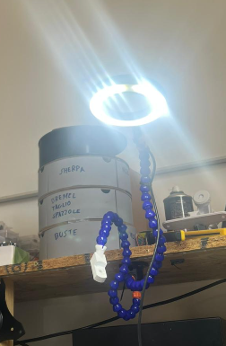
Today i was looking at my workbench light. I like this light a lot, its nicely diffused, i can move it around however i want, and it is a nice color and bright:
It is a usb light and it is controlled by a very “un-complex” controller inline with the usb cable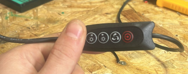 And so i begin to wonder, how hard could it be to hook the button and have a microcontroller interact with the pcb board.
So i opened up the pcb and took a look at it
And so i begin to wonder, how hard could it be to hook the button and have a microcontroller interact with the pcb board.
So i opened up the pcb and took a look at it 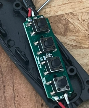 (did not take a foto of the other side) Unfortunately the controller inside is not labeled so i got to probing, it looks like the button shorts a pin of the controller to ground so it is likely to be using a pull-up resistor to read the button state, and the signal side measured, somewhat unexpectedly, 2.5 V when idle. Being USB 5 V i suspect there is some in series shenanigans going on here, but that does not matter to me, all i need to know is that the voltage is below the rated voltage of the esp32-c3 i’m going to use, and that it shorts to ground so i would need to configure the driving pin on our own controller to be an open-drain output to pull down on the pcb pin. So i got working on the soldering.
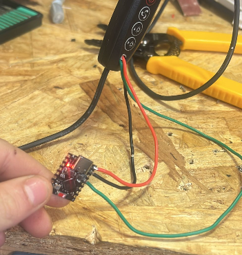 I drilled a hole through using my dremmel and hooked 5v, gnd, and the isolated side of the button. Then i defined the ESPHome configuration as such:
output:
  - platform: gpio
    id: pcb_button_out
    pin:
      number: GPIO4
      mode: OUTPUT_OPEN_DRAIN
      inverted: true # testing showed the logic should be inverted, i can't figure out why

script:
  - id: press_pcb_button
    mode: restart
    then:
      - output.turn_on: pcb_button_out
      - delay: 100ms
      - output.turn_off: pcb_button_out

button:
  - platform: template
    name: "Press PCB Button"
    on_press:
      - script.execute: press_pcb_button
Just as described i defined a pin to be open drain and with inverted logic, and then defined the script to actuate that IO and then defined the actual button Hass will integrate. Uploading it over OTA works and now i can press the button remotely. I think that this project besides being very basic shows the true potential of ESPHome and basic electronics knowledge, without any additional components we are able to command devices whose logic voltage is at or below that of the ESP32-C3 devboard, and a very cheap at that, this incredibly useful integration costed me a whole 2,3 €.
12:43
I later revised the ESPHome to be a switch that keeps track of the state of the light, and if it ever gets desynced i can use the original button to switch the light on and off according to the reported state of the esp32.
3d printer e-stop
I always wanted a e-stop for my 3d printer, and now i can just make one. I grabbed this nice model from printables and printed it out. 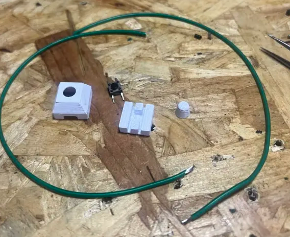 Everything is ready and assembly is very easy and requires just a bit of soldering, although i suggest using smaller wires for this since i had to cut some of it to fit inside the print.
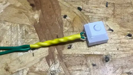 This is the finished product, i twisted and covered with heatsing the initial part to offer some strain relief , then i carefully soldered it to the already existing esp32-c3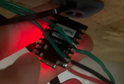
On the software side i defined the button on ESPHome:
binary_sensor:
  - platform: gpio
    id: gpio3_button
    name: "GPIO3 Button"
    pin:
      number: GPIO3
      mode:
        input: true
        pullup: true
      inverted: true
And then with a quick flow on node-RED i can trigger through the moonraker api a emergency stop:

Granted this is not the best, it is relying to quite a big stack to basically just stop sending gcode comands to a printer. A proper estop would involve cutting power to the printer interrupting L and N going to it.